Cable-to-device connections can accumulate contaminants, causing them to heat up quickly, which can easily damage or destroy the cable and the mobile device. The fix: better circuit design with temperature monitoring.
Although the popularity of wireless charging for smartphones and other mobile devices is growing quickly, charging cables are unlikely to disappear completely anytime soon. That’s because wired charging offers significant advantages over wireless charging for some users — primarily that wired charging offers far greater charging speed.
The USB Power Delivery ( USB-PD) and USB Type-C Connectors and Cable Assemblies specifications developed by the USB Implementers Forum (USB-IF) are central to the latest generation of wired charging solutions. The USB Power Delivery Specification enables the maximum functionality of USB by providing more flexible power delivery along with data over a single cable.
Fast chargers and cables compliant with USB-PD and USB Type-C specifications can support charging power levels up to 100 W. Depending on the device involved, that means that they can recharge a phone or other device much faster than a wireless charger. A wired charger with a long-enough cable also allows users to keep interacting with their devices while they’re recharging, which is a major advantage for the phone-addicted among us.
As important as these advantages are to users, it’s equally important for designers to consider the safety issues associated with power and temperature management at the cable-to-device connection. Without proper circuit design, including temperature monitoring, cables and connectors can accumulate contaminants inside the connection, causing them to heat up quickly, which can easily damage or destroy the cable and the mobile device.
The basics of USB Type-C wired charging
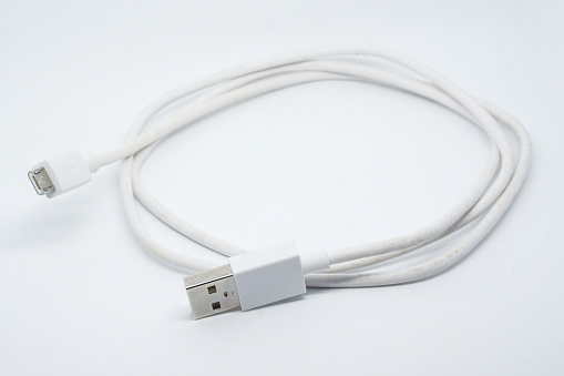
In any charging system, three individual items must work together — the device being charged, the cable, and the charger. USB Type-C (or USB‑C) cables have one or more symmetrical (and, therefore, reversible) 24-pin connectors. USB‑C chargers have an AC plug on one end (for plugging into a wall outlet) and either a cable with a USB‑C connector on the other (for plugging into the device to be charged) or a USB‑C output port for plugging in a USB‑C cable.
From a safety standpoint, USB‑C cables must be capable of carrying appropriate voltages and currents. For chargers with captive or fixed cables, the cables must be capable of handling the charger’s maximum voltage output. Cables with USB‑C plugs on each end must be capable of handling 21 V and at least 3 A. Cables that incorporate special e-marker ICs can carry 5 A of current. Any device placed in the path of power, especially protection devices, must also be capable of withstanding these levels of voltage and current.
The sources of USB‑C charging damage
The pin pitch of USB‑C connectors is 0.5 mm ― much tighter than the 2.5-mm pin pitch in USB Type-A connectors. This tighter pitch significantly increases the risk of a fault that could cause a thermal event. When connector pins become deformed or dust, metal particles, hair, or other debris gets stuck in a USB‑C cable connector, a resistive fault can be created from the power line to ground. These resistive faults can cause a dangerous temperature rise while increasing current only minimally. Damage to both cables and devices, even fire, has been reported.
The traditional approach to protecting USB cables from overheating involves locating either a polymeric positive temperature coefficient (PPTC) device or a mini-breaker (also known as a thermal cutoff) on the VBUS power line. The chosen device would be placed on a printed circuit board inside the connector to sense the temperature rise created by the resistive fault.
However, using this approach when attempting to protect against up to 100 W can challenge design engineers. One of the drawbacks of adding a protection device in the path of power is that its resistance, even if it’s just milliohms of resistance, can contribute to meaningful power loss, making it more difficult for manufacturers to meet mandatory efficiency requirements.
The close confines of a USB‑C connector can also make it difficult to fit a protection device inside. PPTCs suitable for protecting 60-W chargers typically have a 1210 (3.2 × 2.5 mm) footprint, and mini-breakers are often even larger. PPTCs and mini-breakers meant to protect 100 W would need to be even larger. In addition, mini-breakers have relatively weak mechanical structures, and the cable assembly process has the potential to deform the bi-metal materials from which they’re constructed, which would prevent them from providing protection during a heating fault.
New protection devices in new locations
One way to address these disadvantages is to place a different type of protection device in the communication channel (CC) of the USB‑C connector, rather than on the VBUS line. One of the newest devices developed to protect USB‑C cables against overtemperature conditions is the compact (2.0 × 1.2 mm) PolySwitch setP digital temperature indicator . The setP device senses a temperature increase, then “alerts” the system to shut down the flow of power.
Here’s how it works: a setP digital temperature indicator is placed on the connector’s CC line, and when it senses temperatures higher than 100°C, it switches from a low-resistance state to a high-resistance state. This heightened resistance causes the voltage on the CC line to increase beyond the value defined by the USB Implementers Forum (USB-IF) to determine if the source and sink are detached.
The charging system assumes that the cable has become detached because the voltage is higher than the value set forth in the specification, so the charging system turns off the power through the VBUS line. This prevents the connector, cable, and device being charged from overheating. Once the user disconnects the cable and removes the debris from the connector, the cable can resume normal operation.
With a compact 0805 (2.0 × 1.2 mm) footprint, setP devices are at least 30% smaller than most other solutions used for this application in the past. Their rigid physical structure also allows them to withstand modern cable assembly and molding operations reliably. They’re well-suited for use in USB‑C charging cables, USB Power Delivery charging cables, and chargers with captive USB Type-C cables.
Conclusion
USB‑C cables offer owners a fast, uncomplicated way to recharge mobile devices and transfer data. Now, with the development of a new solution for temperature indication, they can be confident that the process will remain safer as well.
Todd Phillips is the global market manager for the Electronics Business Unit at Littelfuse, Inc. He joined Littelfuse as a sales engineer in 2006 for the industrial business unit. Todd joined the electronics business unit in 2011 as a regional sales manager. His current focus is on vertical market segment activities for the data center and cloud infrastructure, LED lighting, and the mobile and wearable markets. He received his BSEE from Milwaukee School of Engineering.